konstruktor 253 Napisano Decembar 25, 2011 Zainteresovan, 640 postova Lokacija: Valjevo Motocikl: etz 150 ,Yamaha xs 250 Prijavi odgovor kao problematičan Sad je vec dosta jasnije jos koliko sutra rasturam staro napajanje pa cu da probam ,javljam rezultate Citat Podeli ovaj odgovor sa prijateljima Link to post Share on other sites More sharing options...
guja011 167 Napisano Decembar 25, 2011 Drug član, 1847 postova Lokacija: Beograd Prijavi odgovor kao problematičan evo slike jedne grozote al čisto zarad principa štipaljke i prstena (ovo na slici je za hall senzor,ignoriši tu budževinu, crveno našvrljano je kalem na 1 polutki prstena) Citat Podeli ovaj odgovor sa prijateljima Link to post Share on other sites More sharing options...
Hacky 599 Napisano Decembar 26, 2011 Zainteresovan, 542 postova Lokacija: Beograd Motocikl: Honda CBF 1000 Prijavi odgovor kao problematičan Da li pasuje CDI od Afrike rd07 na rd04? Treba mi 100% siguran odgovor. I sta je najgore sto moze da se desi ako nisu kompatibilni a ipak se zamene? Citat Podeli ovaj odgovor sa prijateljima Link to post Share on other sites More sharing options...
VladCan 249 Napisano Decembar 26, 2011 Svrati ponekad, 190 postova Lokacija: Toronto, Ontario, Canada Motocikl: 2002 Suzuki GSF1200S Bandit, 2005 Yamaha Majesty 400 Prijavi odgovor kao problematičan VladCan, neće pušta link Izgleda da su na Maximum-suzuki resili da teraju ljude da se registruju da bi citali taj thread. Registracija je besplatna pa to ne bi trebao da bude problem, ali mogu ija da kopiram post po post. Evo ga prvi, a vi vicite ako vas zanima da prenesemi ostale: I finally got around to properly wiring all my electrics this winter, so I thought others may benefit from my no-frills approach. After several years of adding anything from heated grips and air-horn to heated jacket liner and fog lights my wiring was so messed up that the battery started to resemble the Flying Spaghetti Monster (I was touched by His noodly appendage ). It was time to put some order in that chaos, and after a lot of careful deliberation I decided to take the approach based on following principles: - Functionality. Dooh! I do have a few uncommon functionality requirements though, such as being able to turn everything off with one switch even while riding. - Accessibility. Components need to be reasonably accessible for expansion/troubleshooting. Elements used in normal operation, such as switches, should be within easy reach wherever possible. - Simplicity. Minimize the number of components as much as practicable. One wire is always better than two, no wires even better (yes, you don't always need wires). - Versatility. Ability to accommodate many different devices/connections, both current and future ones. - Availability and affordability. Components should be generic and widely available in stores (no specialized, Internet-order-only stuff). Price is important, but not a big issue - simpler is usually cheaper anyway. - Minimal or no sacrifice of under-seat storage space. The pan on top pf the battery is out of the question because it has to be removed every once in a while and I just don't want to dedicate the entire toolbox compartment to a few dozen cubic centimeters of wires and relays. - Aesthetic appeal of all components that are not normally visible is irrelevant. I also didn't pay much attention to color coding or marking - it's my bike and I know what/where everything is. - Everything needs to be securely fastened and reasonably protected from vibrations, heat, flexing/bending, water/moisture, etc. Lessons learned: - Using chassis ground wherever possible (and it was possible practically everywhere) proved a great idea. Not only did it save me a lot of wiring, but in some instances eliminated routing through areas where the wires would be frequently bent (around steering stem) snagged or exposed to heat. I never needed to drill or tap into any wires for grounding because an unused screw hole on the frame was always near by (plenty of those on the faired Bandit). - You don't need a switched power supply (off when the ignition key is in off position) for circuits that use their own harness with a relay because their relay coils are powered from an already switched source. Consequently, the main relay that supplies power to the distribution block proved practically redundant. If I was doing it again from scratch I'd use a high power switch (with a block condenser) just so I can turn everything off when working on the electrics. The distribution block would have half the number of terminals too. - Plan carefully and examine your bike thoroughly, and you can make the whole setup very neat and functional. I have six relays, two modulators, two diodes, three switches and a LED indicator set up to power air horn, driving lights, headlights, heated grips, heated clothing, GPS, etc., but I bet you I have shorter total wire length than most people use just to hook up heated grips. And I would optimize it even better if I knew when I started what I know now. - You don't need a fuse for every circuit. A main ~30A fuse is a must, and it should be as close to the battery as possible. Pretty much everything else is elective, especially if the wiring is thick enough. Thanks to the careful load distribution I ended up with only two extra fuses, and I consider it enough. Pay attention to the fuses that protect the existing circuits you use and don't overload them. Calculate the load on new circuits, dimension the wiring and fuses accordingly and you'll be able to use a single fuse for more than one device. For example, my driving lights and air horn are powered through one 30A fuse, while the headlights are wired through the main harness fuse of the same size, so if one set of lights shorts the other will remain operational. Or, if my horn shorts, just one set of lights will go with it - the less important pair. Note that this approach makes troubleshooting electrical gremlins somewhat harder, but I'm not worried since I over-engineered practically everything by 20-30% and it's all mechanically and electrically sound. My heated grips, for example, are not fused at all. They are powered from the starter push button switch that is already fused and they draw only 35W (2.5A max). I may add an in-line fuse when I get a hold of some of those posi-lock fuse holders, but it's not critical. - You don't need 10 gauge wire for every lead, let alone thicker. The shorter the wire, the thinner it can be for the same resistance (read: voltage drop), and you certainly don't need anything thicker than 18 gauge to power the relay coils. In my setup it boiled down to 10AWG for the two main positive leads from the battery/distribution block to the front of the bike (just behind the steering stem), 14AWG for almost all other load bearing wiring (headlights, horn...) and 18 for all relay coil power. I found 14AWG to be the best for minimum voltage drop without compromising wire flexibility, but if you can find 12 gauge that is as thin, flexible and UV/heat resistant more power to you. You can achieve better results by shortening the wires with careful planning and routing than you can by stuffing 8AWG everywhere. On top of it all, anything over 14AWG gets increasingly difficult to crimp, bend, solder... - Measure three times - cut once . Leave extra length/space for everything until it's time to seal the deal. Even then, count on having to cut, re-position and even occasionally re-install, so make sure you have plenty of material. For example, I found that having a lot of zip-ties especially unlock-able/reusable ones is quite a treat. Distribution block The wiring harness had enough slack, so I moved it into the toolkit compartment, freeing up the space between the battery cover and the toolkit compartment. Not much room there, but the distribution block fit just fine: Note the shiny screw on the frame in the upper left corner of the picture. I could have wired the negative lead for the distribution block to it instead of the battery negative terminal, therefore making the setup a little easier to work on and battery more accessible. Plenty of unused and pre-tapped screw holes on bandit's frame, many of which will prove quite handy for grounding... Here is what I need powered, with current draw and fuse figures: - GPS and USB charger - (under 200mA) 1A micro fuse - Heated clothing and charging connector - 100W (8.3A) fuse 10A - Driving lights - 2x50W (8.5A) fuse 10A - Headlights - 55+60W (2x5A) fuse 15A - Heated grips - 35W (2.5A) fuse 5A - Stebel air horn - 220W (18A) fuse 20A The first two should be constantly powered, i.e. connected straight to the battery (through the main 30A fuse, of course). Others should have power only when the key is in ON position. They should NOT be on when the key is in "park" position, so I will not power the relay coil from the license plate/running light as others usually do. I will be able to turn these off manually and all at once even if the engine is running. The wiring diagram: Relays Relays are a very important part of the wiring design. They are several reasons to use them instead of just wiring directly through a switch, especially for powering high current devices such as fog/driving/headlights, aftermarket horns, etc. They basically allow us to turn on/off a device that draws 30A with a switch that can't handle more than 1A, while still providing full 30A to the device with minimal to no voltage drop. A typical generic 30-40A/12V SPDT (single pole, dual throw) automotive relay looks like this: , and here is it's schematic and pinout diagram (note that most relays have the schematic printed on their case): Some more info on different types of relays can be found at http://www.the12volt.com/relays/relays.asp. If/when in doubt, I suggest to purchase SPDT as they can be used as SPST (single pole, single throw), but not the other way around. The difference in price is usually negligible, and you can always remove, isolate or just ignore the extra pin/connector. An example of a generic relay power supply/harness: - Thick lines are the only ones that need to be sized for the current draw of the device. All other wires can be quite thin (20AWG or even thinner) as the relay coil draws little current (typically under 0.2A) and is not very sensitive to voltage drop. - You can use pretty much any switch, or tap into any existing switch on the bike without worries that it will burn due to heating or sparking caused by high current. - The relay coil positive supply (86) can be hooked up anywhere, even without the switch. Practically you can just tap into any wire that's running 12V when you want the device turned on. For example, if you want something on when your left turn signal is on just tap into it's positive lead to power the relay. - Relays don't really "care" about polarity. They are going to close/open the same way, regardless of how you hook up their coil, and it certainly doesn't matter which lead they are switching (you can use them to disconnect the ground wire (-) if you want to). Ergo, connections 85 and 86 are interchangeable (doesn't matter which wire goes where), and so are 87 and 30. Knowing this can help you better arrange the wires/connectors on the relay for a neater setup. Here's another wiring diagram, air horn implementation: Heated clothing, Battery Tender and auxiliary power connector - The standard "quick connect" plug (right) is connected to an always powered connection on the distribution block. It's polarized so the "naked" pin is negative to prevent short circuit. It also has a cover and it's held by a velcro strap to the frame under the left side of the tank when not in use. - The quick connect - coaxial adapter (left) is used to connect the portable heated clothing controller (heat-troller: http://www.warmnsafe.com/images/product-dpcoax.jpg). - Battery tender connects directly to the quick connect plug as it uses the same standard. - A quick connect - female cigarette lighter plug adapter is used for any other device, from the air pump to Dc-AC converter, to cell phone charger. GPS/USB power adapter NOTE: The USB power was eventually supplied in a quite different way. I'm leaving this part here because it's a valid alternative, but those that want it done the neatest possible way should just skip to the next post. This is what came with my GPS, but you can find something similar for under $10 shipped at dealextreme.com (my favorite online cheap gadget store): Of course, I wasn't just about to take this big and non-waterproof cable-with-a-bulge, plug it in an even uglier cigarette lighter socket and forget about it until it blows the fuse or burns my GPS. So, I bought a smaller one from the site above and stripped it like so: I detached the indicator LED (it's not necessary for the circuit to operate) and reduced the current draw of the adapter with no device attached to mere 20mA. Even when it powers my GPS I can leave it on for hours without worrying it will drain the battery. I'll attach a 1A micro fuse just in case, stick it into a heat-shrink tube and Bob's your uncle . I'll take the big USB female connector off and wire the cable directly to the PCB, of course. Citat Podeli ovaj odgovor sa prijateljima Link to post Share on other sites More sharing options...
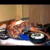
exman 231 Napisano Decembar 26, 2011 Svrati ponekad, 306 postova Lokacija: Bgd N44 44 14 E20 27 10 Motocikl: KTM 525exc Prijavi odgovor kao problematičan Imam problem koji sam postavio u Garaza/KTM: prilikom rasturanja polurama sam razvezao kontakte sa akomulatora. Sad sam stigao do sklapanja pa ne znam gde mi je isla zica sa CDI, na masu ili na + akomulatora. Na njoj imam prisutan napon sa akomulatora, a na elektro semi je data kao da zavrsava na masi?! Citat Podeli ovaj odgovor sa prijateljima Link to post Share on other sites More sharing options...
guja011 167 Napisano Decembar 26, 2011 Drug član, 1847 postova Lokacija: Beograd Prijavi odgovor kao problematičan nemam šemu , al najjednostavnije je uzmeš malu sijalicu npr signalnu ili iz migavca, pa preko nje spojiš tu žicu na masu. onda meri šta imaš na crnoj. poenta je da sa mernjakom kakav imaš, i najbednija struja se prikazuje kao 12 volti , jer je mernjak visoke otpornosti. mada u startu ta papučica mi deluje kao "za na masu" mnogo je gola, vidi ove 2 što idu na + baterije . imaju bužir maksimalno navučen Citat Podeli ovaj odgovor sa prijateljima Link to post Share on other sites More sharing options...
guja011 167 Napisano Decembar 26, 2011 Drug član, 1847 postova Lokacija: Beograd Prijavi odgovor kao problematičan Da li pasuje CDI od Afrike rd07 na rd04? Treba mi 100% siguran odgovor. I sta je najgore sto moze da se desi ako nisu kompatibilni a ipak se zamene? 07 da, 07A jok. a i šta je problem sa tvojim postojećim cdijem. prvo se cdi ako može sredi a ako ne onda gledaš zamenu. dakle gukni problem: Citat Podeli ovaj odgovor sa prijateljima Link to post Share on other sites More sharing options...
konstruktor 253 Napisano Decembar 26, 2011 Zainteresovan, 640 postova Lokacija: Valjevo Motocikl: etz 150 ,Yamaha xs 250 Prijavi odgovor kao problematičan Danas iscupao malog zutog iz napajanja za komp,presekao i ispolirao presecene strane,precnik precenog ferita je fi 13 tako da ce izgleda biti mesta i za kabal i za namotaje.Pitao ortaka da namota,medjutim problem ne moze na masini da mota mora rucno.Sad izgleda da cu ja to raditi,mora li bas 100% da bude namotaj do namotaja.Jos ako ko ima preporuku za debljinu zice i broj namotaja pa da pocnem. Citat Podeli ovaj odgovor sa prijateljima Link to post Share on other sites More sharing options...
guja011 167 Napisano Decembar 26, 2011 Drug član, 1847 postova Lokacija: Beograd Prijavi odgovor kao problematičan kako samo fi 13? čak i za fi rupe, to je malo. izlazni žuti je valjda veći od toga. što se tiče debljine žice sve što može u junačke ruke a da ne iskidaš je dobro-znači od 0,1mm pa naviše. ne možeš motati iovako red do reda kada je u pitanju prsten (različit obim unutrašnje i spoljne strane) nego lepo slaži na unutrašnjoj a spoljna kako legne. npr 50ak namotaja u jednom sloju, pa fiksiraš sa.. naprimer lakom za nokte ili sličnim prigodnim brzim sredstvom a lako nabavljivim pa onda novi red itd. slobodno razvuci preko cele polutke. kada namotaš, sastaviš polutke pa tako sastavljeno uglaviš u štipaljku. ako koristiš metalnu, nešto formalne izolacije između namotaja i lima štipaljke za svaki slučaj i onda zalij epoksijem ili sličnom masom. 1 Citat Podeli ovaj odgovor sa prijateljima Link to post Share on other sites More sharing options...
konstruktor 253 Napisano Decembar 26, 2011 Zainteresovan, 640 postova Lokacija: Valjevo Motocikl: etz 150 ,Yamaha xs 250 Prijavi odgovor kao problematičan Fi 13 je unutrasnji promer prstena a spoljni nisam ni merio, cini mi se da imam ceo kalem 0.15 lak zice pa cu sa njom.I ja sam planirao da zalijem eposkijem u stipaljkama,a celu elektroniku da spakujem u kuciste od starog fena pa ce jos i da izgleda kao prava strobo lampa.Kad zavrsim motanje potrazicu ko moze da mi uradi plocicu pa juris na lemljenje.Korisna je ovo sprava lako se sa njom proveri paljenje a posebno je dobra za proveru da li CDI radi kako treba. Citat Podeli ovaj odgovor sa prijateljima Link to post Share on other sites More sharing options...
guja011 167 Napisano Decembar 26, 2011 Drug član, 1847 postova Lokacija: Beograd Prijavi odgovor kao problematičan Hacky, vidi pp. konstruktor, pcb nije problem, mogu ja da ti uradim. mada mi se ideja sa sažvakanom kineskom lampom više sviđa, minijaturno je pa je time i lako za nosati. ne zaboravi da je potrebno da bele ledare budu u snopu jer je to ipak slabije svetlo čak i sa haj brajtnes ledarama. uostalom, nek proradi prvo, posle je lako za upakivanje.. Citat Podeli ovaj odgovor sa prijateljima Link to post Share on other sites More sharing options...
guja011 167 Napisano Decembar 26, 2011 Drug član, 1847 postova Lokacija: Beograd Prijavi odgovor kao problematičan zaboravih, VladCan, sjajno napisano! Citat Podeli ovaj odgovor sa prijateljima Link to post Share on other sites More sharing options...
VladCan 249 Napisano Decembar 26, 2011 Svrati ponekad, 190 postova Lokacija: Toronto, Ontario, Canada Motocikl: 2002 Suzuki GSF1200S Bandit, 2005 Yamaha Majesty 400 Prijavi odgovor kao problematičan zaboravih, VladCan, sjajno napisano! Hvala, evo i ostatak: I thought I was supposed to be able to edit my own messages, but no can do . Anyway, here are some more pictures with descriptions: The primary distribution relay is the black cube on the right side, just under the hex screw on the frame. There's just enough space for it there - it's bolted on to the starter relay bracket. It's a generic 12V/40A automotive relay, sold in car part stores for $10-15. The switch for the relay + lead (not seen in the picture) is right under the relay, behind the frame, mounted in a hole drilled through the plastic fender. As you can see, the negative lead for the distribution relay is connected to the starter relay mounting bolt. I'm using the frame to connect negative wires whenever possible. It happens to simplify the setup and the frame has less resistance than any gauge wire I may use. All the wires that power relays are as thin as practical. You definitely don't need thicker than 18 gauge because relays draw very little current compared to other equipment (I measured mine at 0.15A = less than 2W). Here are some tools that will help you with wire size, power consumption, fuse value, etc.: Wire gauge charts and calculators: http://www.denningelectronics.com/wiregauge.htm http://www.powerstream.com/Wire_Size.htm Ohm's law calculators: http://www.angelfire.com/pa/baconbacon/page2.html http://www.the12volt.com/ohm/page2.asp http://www.ohmslawcalculator.com/ohms_law_calculator.php Pay attention to the white plastic cover on the starter relay. It shields the relay connectors and thick cables that lead to the battery on one side and to the starter motor on the other. The screw that holds the cable from the battery positive can be easily used to connect the positive for the wiring harness, therefore eliminating the need for any additional connections on the battery itself (it's under the white plastic shield, on the side that faces the battery). It's a very neat solution that I haven't implemented only because of the limited length of wire I had at hand. The positive lead to power the relay coil is hooked up here (the grey connector). - The connection was made by cutting the orange/yellow wire from the unused stock connector under the tank. This wire is powered only when the ignition key is in the "ON" position, just like I want. I don't want any of the auxiliary circuits/devices powered when the key is in "off" or "park", so tapping the running lights was out of the question. - The grey connector is "posilock", a great way to quickly and securely connect wires without soldering or electrical tape, and they are almost infinitely reusable and reconnectable. They are a bit pricey, but I bought them in a surplus store . More details here: http://www.posi-lock.com/ The red wire that loops back from the battery terminal has the in-line 30A fuse and goes straight to the distribution block. It's neatly routed under the rubber cap that protects the + terminal from short circuit. As mentioned earlier, I would have connected it to the starter relay which I think is a much neater solution if only the wire was long enough. The negative (ground) for the distribution block is also connected directly to the battery. It's the yellow-ish wire below the frame at the bottom of the picture - no fuse or protective/isolating cap needed here. In hindsight, I should have connected it to the frame via the unused bolt hole (see the first post - the screw in the upper left corner of the picture). Combined with the starter relay connection maneuver it would make the whole setup very clean. There would be no extra wires connected to the battery, i.e. there would be no change from stock. No potential issues with washer thickness and bolt reach, plus much simpler and easier disconnecting and/or taking the battery out. Very neat indeed! A few more interesting bits: My universal garage door opener key-chain remote uses a 12V battery (just like many other remotes), so wiring it was a no-brainer. I soldered wires to the battery terminals, soldered the switch short, sealed the case with some rubber sealant and velcro-ed it to the side of the toolkit compartment. It's like custom fitted in that corner . The leads are hooked up to the right turn signal (I turn right to enter my garage ) and voila! I advise against hooking up to any power that stays on for long, like brakes or high beams, because the remote designed to run for short periods, just like turn signals do. The blue circle behind the seat bracket is the brake light modulator. In the background you can see a grey "posilock" connector on the + lead for the LED turn signal mounted on the Givi luggage rack. The negative is supplied straight from the rack itself, so there are no other wires. Want your headlights off when starting the bike? Here is a neat mod (copied from this thread: http://www.maximum-suzuki.com/forums/index.php?topic=77278.25 , thanks to MSerfozo for the idea): The pins are marked the same on all relays I've seen. The relay itself is a plain vanilla 30-40A SPST or SPDT (no difference for this application). http://www.radioshack.com/product/index.jsp?productId=3020762 You can use pretty much any diode that can handle 1A at 12V, like 1N4001 or 1N4003 (http://www.radioshack.com/product/index.jsp?productId=2036268). The basic rule of thumb if you don't know what you have is that it's OK if it doesn't burn right away or gets too hot to hold between your fingers . You can't do no harm if you reverse it's polarity - it just won't pass any current. Important notes: - This can be implemented only exactly as shown on headlights that have both beams/filaments on when the switch is in the high beam position. The switch has to be in the low position when the bike is turned on, or both high/low beams will be on. - For headlights that turn on high/low beams/filaments independently (i.e. they are never both on at the same time) you can revert this diagram if you wish - it doesn't matter which light will be used as "off until braking". - To the best of my knowledge, this scheme by itself cannot be used to improve the wiring harness output, but can be combined with a new harness circuit. In order for the light to turn off when the ignition is off, the "low beam in +" lead has to come from the stock/OEM wiring harness - not directly from the battery. Otherwise, the light would stay on permanently once the relay closes for the first time, regardless of the ignition key position. First night ride impressions: - Light output is considerably better. Low, high and fork mounted lights are all at full brightness all the time. No dimming, flickering... - Low beam throw pattern is barely adequate due to the faded reflective coating in the housing. Nothing I can do about that until I replace it with Hella. At least it doesn't appear to blind anyone... - High beam is quite good. Good enough that when I turn it off it makes low beam feel positively pathetic. I may just aim it a little higher. - Fork mounted lights do improve visibility, but not as much as I expected - they throw more to the side than to the front. On the other hand, I'm sure they make me much more visible, day or night. They also stayed put even when I was riding over some pretty bumpy railway crossings. All in all, if I could ride with high beam on all the time there wouldn't be any need for further improvements. BTW, I have HIR bulbs in both headlights. As said before, I'm quite happy with both lights modulated in high beam position - I's sure it helps me stand out during the day, and there is no confusion with turn signal, no matter how rarely it happened before. I've been running all the major power devices together most of the time without any issues. Went on a couple of long day rides with hi/lo beam + fork lights + heated grips constantly on and haven't noticed any anomalies in either charging system or performance of other devices like GPS, turn signals, etc. I've also turned the heated vest on full along with all other stuff and nothing blew, although I couldn't do it for long or I would roast myself . I even blew the horn (biggest current draw by far - 18A) for a few seconds just to be sure - still barely dimmed the headlights. And the bike still has it's 2002 OEM battery. 22,600Km update: Just washed the bike thoroughly preparing for winter projects/storage. Everything is in place and fully functional - not a single component has failed or gave me any trouble yet. Here's what I plan to do next: - I sourced a stock headlight in very good condition. My OEM is pretty much beyond repair (faded reflectors, cracked lenses, outer lense showing signs of wear, black dust again...), so I'll try to make this one last as much as possible. I don't know what I'm going to do yet, but I have to somehow prevent things from moving even by a little bit. Will retain stock bulbs though, HIDs cannot be modulated and high power bulbs would burn the reflector fast. - Turn signals are back to stock and will remain that way. The only modification is that the rubber mounts are removed to make them shorter. Added vibration does not seem to affect the rear ones that are screwed on to the Givi rack and front ones are still suspended in rubber holes anyway. No decently priced LEDs even come close to the 1157 brightness. I did paint the interior of the turn signal housings with chrome spray paint which seems to add to the brightness quite a bit. People riding behind me tell me they are all but impossible to ignore even in bright sunlight. - One of the 3W led stop lights fell out of it's socket. I'll need to reassemble and glue it together properly. Will spray-chrome the brake light reflector while I'm at it. - Fabricate the mirror mounts for auxiliary lights. Fork mounts have proven durable enough, but mirror position will make them much easier to adjust and position them considerably higher for further reach down the road. - Other mostly cosmetic/comfort stuff not relevant for this particular thread (handlebar change, fixing paint here and there...). I found a better, easier and more powerful solution for the USB power supply, the VMP3203-High Efficiency DC-DC Module: https://www.dealextreme.com/p/vmp3203-5v-high-efficiency-dc-dc-module-47817 Compared to the 7805 IC that currently powers my GPS, this module outputs three times the juice - 3A, or enough for six USB-powered devices. It's much more efficient too (98%), so it needs no heat sink. Just like the IC, it does not draw any measurable current when no devices are attached, so it can remain permanently connected to the battery. I'm not absolutely sure, but I think it's overload protected, so it doesn't need a fuse either (I can afford to burn it at that price anyway). Datasheet is here: http://v-module.chejian6.com/info.aspx?id=25 I decided to use this other item as a housing for it, so I'll have a lighter socket plus two USB powered sockets. Just stick it under the seat and Bob's your uncle . https://www.dealextreme.com/p/2-500ma-car-cigarette-powered-usb-adapter-charger-with-extra-cigarette-power-socket-dc-12v-24v-29651 Why didn't I just use this adapter/charger as is? It's too complex, inefficient and unreliable, so I'll just use it to provide housing and connectors for the DC/DC module. 2 Citat Podeli ovaj odgovor sa prijateljima Link to post Share on other sites More sharing options...
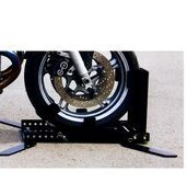
DjordjeMijailovic 2620 Napisano Januar 8, 2012 Strucnjak, 1615 postova Lokacija: Novi Sad - Šabac Motocikl: CRF300L Prijavi odgovor kao problematičan Kako se tacno zovu ove buksne? Treba da ih kupim a ne znam sta da trazim. Citat Podeli ovaj odgovor sa prijateljima Link to post Share on other sites More sharing options...
Iron_Floyd 395 Napisano Januar 10, 2012 BIG ENDURO FREAK, 640 postova Lokacija: Novi Sad; Zrenjanin; Motocikl: Honda TRANSALP XL600V 1987 Prijavi odgovor kao problematičan Kako se tacno zovu ove buksne? Treba da ih kupim a ne znam sta da trazim. ja nisam dosad ni pitao za tako nesto jer mislim da tako nesto nema kod nas... ali ako ima... uzimam pod obavezno Citat Podeli ovaj odgovor sa prijateljima Link to post Share on other sites More sharing options...
VladCan 249 Napisano Januar 10, 2012 Svrati ponekad, 190 postova Lokacija: Toronto, Ontario, Canada Motocikl: 2002 Suzuki GSF1200S Bandit, 2005 Yamaha Majesty 400 Prijavi odgovor kao problematičan Kako se tacno zovu ove buksne? Treba da ih kupim a ne znam sta da trazim. ja nisam dosad ni pitao za tako nesto jer mislim da tako nesto nema kod nas... ali ako ima... uzimam pod obavezno ne znam kako se zovu, ali ih ja nikad nisam voleo. Posto se obicno koriste za kontakte koji se retko razdvajaju (na primer, migavci) ja ih najcesce zamenjujem "luster klemama" ili Posilock konektorima (http://posi-lock.com) koje sam nasao na rasprodaji za 15c/komad. Citat Podeli ovaj odgovor sa prijateljima Link to post Share on other sites More sharing options...
Iron_Floyd 395 Napisano Januar 10, 2012 BIG ENDURO FREAK, 640 postova Lokacija: Novi Sad; Zrenjanin; Motocikl: Honda TRANSALP XL600V 1987 Prijavi odgovor kao problematičan Nzm, meni se svidjaju te buksne, jer ne moram da pravim izmene na originalnoj instalaciji i izmisljam toplu vodu.. Citat Podeli ovaj odgovor sa prijateljima Link to post Share on other sites More sharing options...
Alien 603 Napisano Januar 10, 2012 Zainteresovan, 863 postova Lokacija: Beograd Motocikl: R1200GSA Prijavi odgovor kao problematičan Kako se tacno zovu ove buksne? Treba da ih kupim a ne znam sta da trazim. mala je slicica pa nisam 100% siguran, ali deluje kao da su to "metak konektori" (bullet). imas ih u kelco-u (bivsi radio klub). 1 Citat Podeli ovaj odgovor sa prijateljima Link to post Share on other sites More sharing options...
Iron_Floyd 395 Napisano Januar 10, 2012 BIG ENDURO FREAK, 640 postova Lokacija: Novi Sad; Zrenjanin; Motocikl: Honda TRANSALP XL600V 1987 Prijavi odgovor kao problematičan Kako se tacno zovu ove buksne? Treba da ih kupim a ne znam sta da trazim. mala je slicica pa nisam 100% siguran, ali deluje kao da su to "metak konektori" (bullet). imas ih u kelco-u (bivsi radio klub). Bravo! To je to, evo nasao sam http://kelco.rs/katalog/komponente.php?IDgroupweb=6537 Nisam znao da se tako zovu. 1 Citat Podeli ovaj odgovor sa prijateljima Link to post Share on other sites More sharing options...
DjordjeMijailovic 2620 Napisano Januar 10, 2012 Strucnjak, 1615 postova Lokacija: Novi Sad - Šabac Motocikl: CRF300L Prijavi odgovor kao problematičan Bravo ! Meni su potrebni za ugradnju alarma, tacnije za izlaz na migavce. Posto su migavci vec spojeni ovim konektorom, zelim da ne diram postojecu instalaciju vec samo umetnem svoj komad zice izmedju. Ne pominju se velicine. Da li je moguce da postoji samo jedna? Citat Podeli ovaj odgovor sa prijateljima Link to post Share on other sites More sharing options...
Iron_Floyd 395 Napisano Januar 10, 2012 BIG ENDURO FREAK, 640 postova Lokacija: Novi Sad; Zrenjanin; Motocikl: Honda TRANSALP XL600V 1987 Prijavi odgovor kao problematičan Bravo ! Meni su potrebni za ugradnju alarma, tacnije za izlaz na migavce. Posto su migavci vec spojeni ovim konektorom, zelim da ne diram postojecu instalaciju vec samo umetnem svoj komad zice izmedju. Ne pominju se velicine. Da li je moguce da postoji samo jedna? Nzm stvarno, ja kapiram da bi trebalo samo jedna velicina da postoji... ako nadjes u NS, javi u kojoj prodavnici ima.. dal u tehnotronik, orbit ili gde vec... Citat Podeli ovaj odgovor sa prijateljima Link to post Share on other sites More sharing options...
DjordjeMijailovic 2620 Napisano Januar 10, 2012 Strucnjak, 1615 postova Lokacija: Novi Sad - Šabac Motocikl: CRF300L Prijavi odgovor kao problematičan Za 5-6 dana sam u NS pa cu da pogledam. Ponecu sliku za svaki slucaj. Ako nista drugo, narucicu iz BG. Nije neka cena Citat Podeli ovaj odgovor sa prijateljima Link to post Share on other sites More sharing options...
Alien 603 Napisano Januar 11, 2012 Zainteresovan, 863 postova Lokacija: Beograd Motocikl: R1200GSA Prijavi odgovor kao problematičan super su metak konektori, koristio sam ih za sve sto sam dodavao na moj motor. jedina mana im je sto nisu izolovani od vode, ali su tako napravljeni da nema sanse da spoj dva konektora dodirne neki drugi deo (kad se spoje muski i zenski bullet konektor spoj je okruzen plastikom sa svih strana). prava svar su "japanski konektori". oni su isti kao bullet ali imaju silikonsku/gumenu zastitu preko mesta spoja, tako da voda ne moze da udje. nazalost, kod nas ih nisam video u prodaji. mogu se naruciti u louisu http://www.louis.de/_20f942c28bad4b949538762ce162629b5b/index.php?topic=artnr&artnr=10032033 Citat Podeli ovaj odgovor sa prijateljima Link to post Share on other sites More sharing options...
DjordjeMijailovic 2620 Napisano Januar 11, 2012 Strucnjak, 1615 postova Lokacija: Novi Sad - Šabac Motocikl: CRF300L Prijavi odgovor kao problematičan Hmm izgleda da mi japanski trebaju ipak Citat Podeli ovaj odgovor sa prijateljima Link to post Share on other sites More sharing options...
Alien 603 Napisano Januar 11, 2012 Zainteresovan, 863 postova Lokacija: Beograd Motocikl: R1200GSA Prijavi odgovor kao problematičan imaj na umu da ako hoces sve da bude vodootporno - treba da resis i dihovanje spoja zica-konektor, inace dzaba vodootporni spoj dva konektora... . jedna ideja je da zalijes topljenu plastiku (iz "pistolja") tamo gde se zica spaja sa konektorom.. Citat Podeli ovaj odgovor sa prijateljima Link to post Share on other sites More sharing options...


.thumb.gif.3afda113dc924a8797ddc7ad7d8352e2.gif)

.thumb.jpg.0d0060f3b8af91ccc2d023f95385597b.jpg)